Logo

Daniel-Barker.com

ardugauge-img-1.jpg

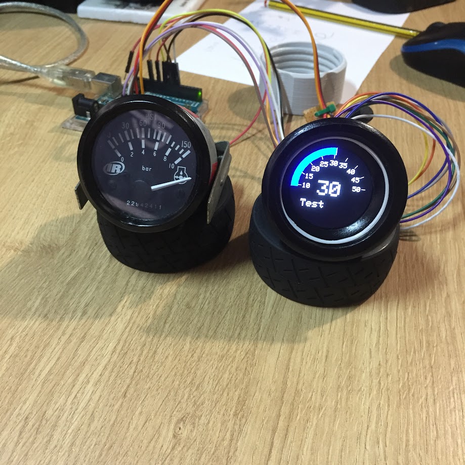
In this project I set out to create a customisable Arduino based automotive gauge - ArduGauge.
The hardware is designed around an Atmega328P microcontroller, the same microcontroller found in Arduino UNOs and Nanos. This allowed me to develop a gauge which is easily programmable whilst maintaining a relatively low cost.
The enclosure is designed to be easily 3D printable and sized as a direct replacement for a conventional 52mm automotive gauge, typically found in older vehicles.

Key features:

  • Custom designed PCB.
  • 1.28" Colour LCD.
  • 4 analog inputs.
  • SPI & I2C enabled.
  • Onboard voltage regulation and filtering.

ardugauge-dev-1.jpg ardugauge-hello-world.jpg

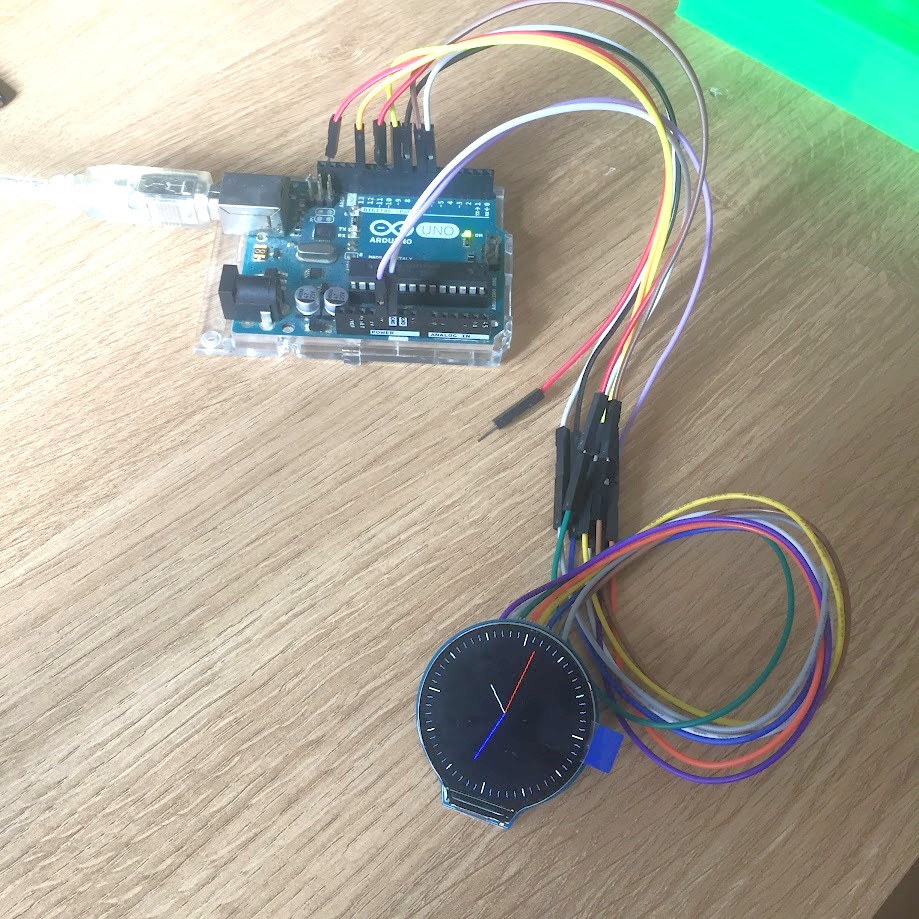
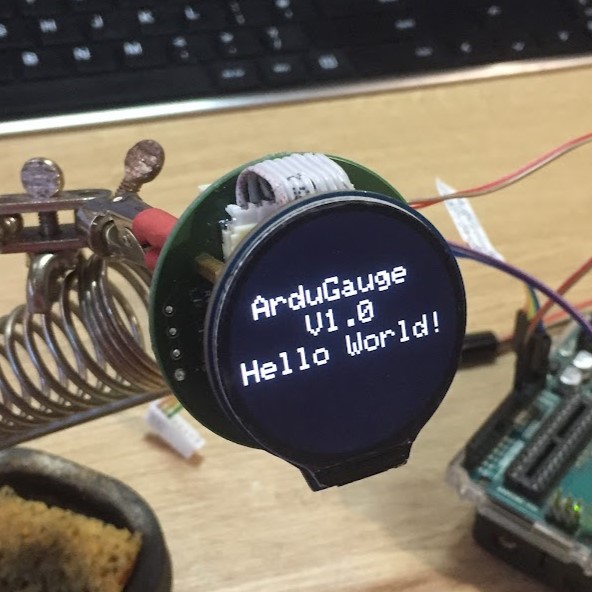
Development started with an Arduino Uno and a round 1.28" LCD.
I become familiarised with the hardware and its limitations to verify that my choice of microcontroller would be suitable. The limiting factor is the rate at which the Arduino can refresh the display; however, this is sufficient for sensors that don’t have rapidly changing values.
Alongside the electronic development, a housing design was created to fit into a 52mm gauge holder/panel hole, allowing it to be a direct replacement for a 52mm automotive gauge typically found in older vehicles. A threaded collar screws onto the gauge body to secure it as found on modern VDO gauges.

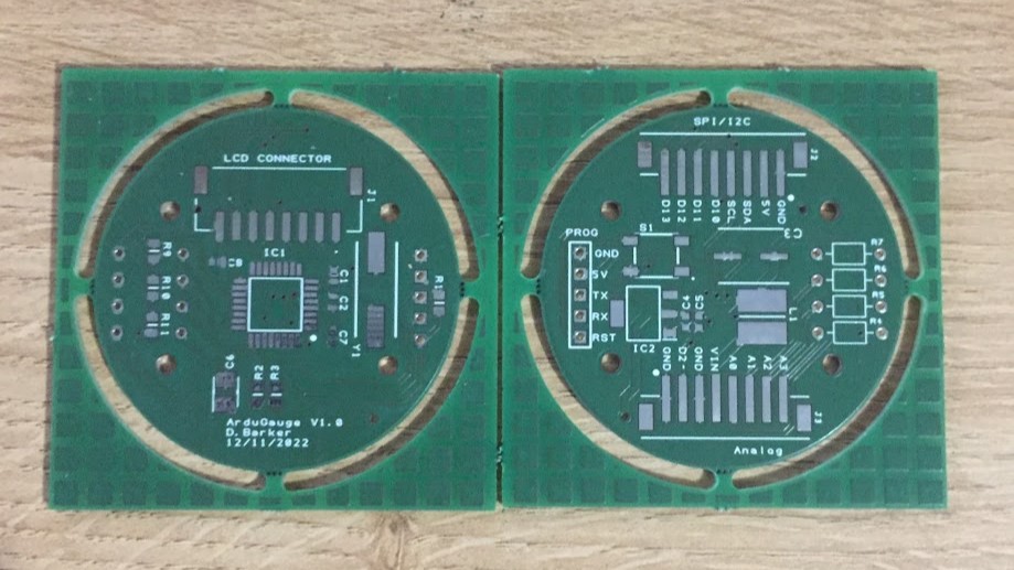
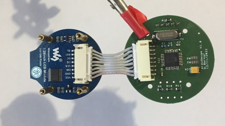
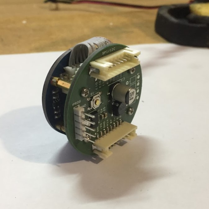
Using Designspark PCB software I designed a round PCB layout which fits within the gauge housing and stacks beneath the LCD.
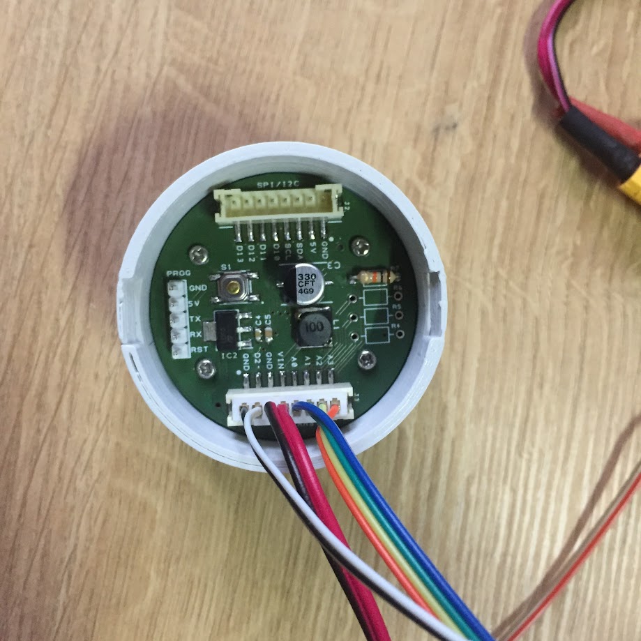
As the intended application is automotive use, an onboard voltage regulator allows the 5-volt Arduino and LCD to be powered from a vehicle’s 12V feed. An LC filter is used to provide noise reduction on the regulated supply line.
All useable I/O pins on the Arduino are accessible via the two JST pins maximising the gauges customizability.
The PCBs were assembled by hand.

ardugauge-pcb-1.jpg ardugauge-pcb-2.jpg

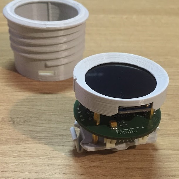
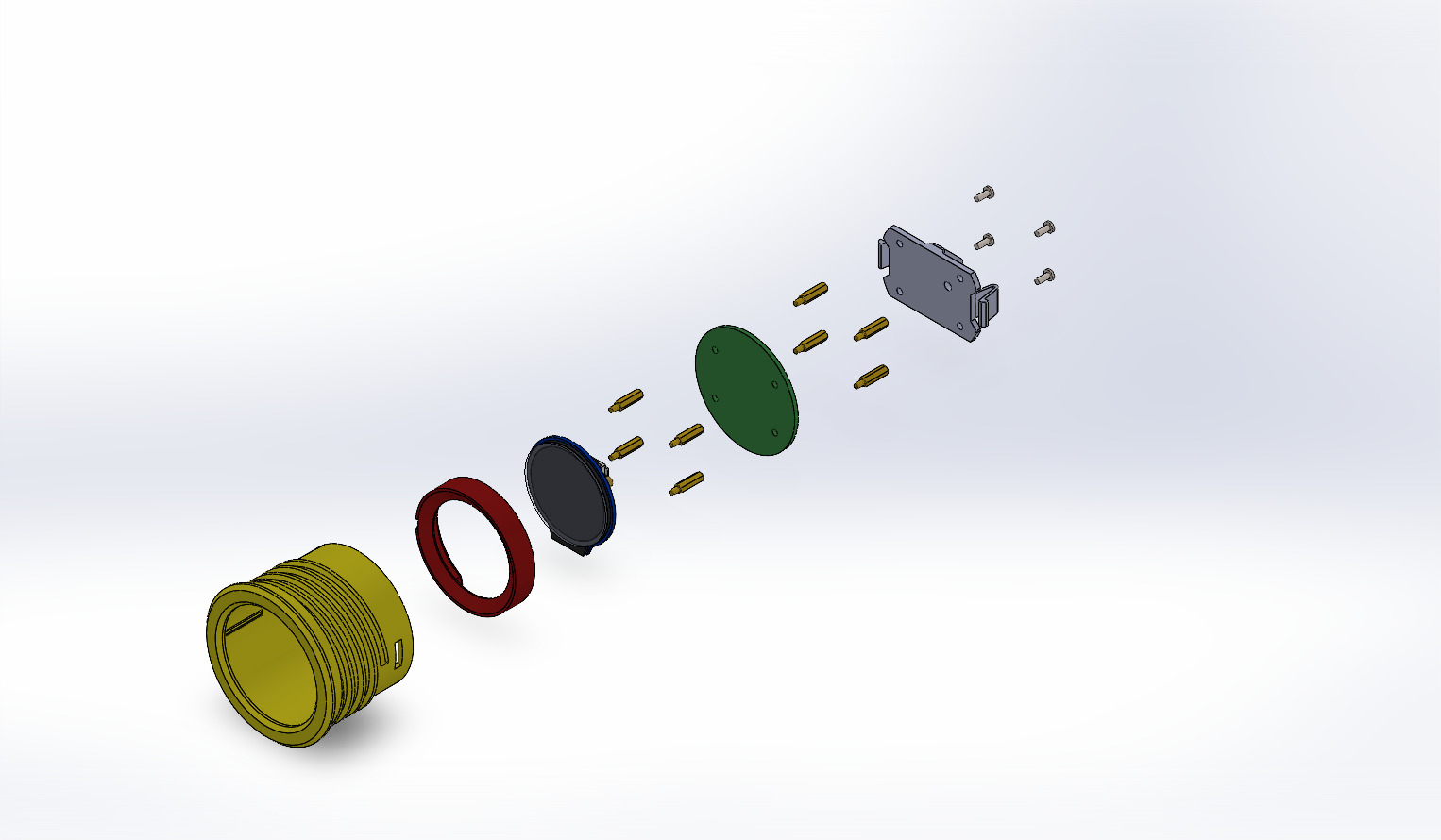
The housing is designed to be 3D printed. It comprises the main body with bezel, a spacer piece which centers the LCD, and a retaining plate which holds the electronics and clips into the main body.
A collar with 3D printed threads screws onto the main body to secure the gauge assembly into the dashboard of the vehicle.

ardugauge-pcb-3.jpg ardugauge-1.jpg ardugauge-2.jpg ardugauge-3.jpg

The customization of the gauge and the range of available I/O allow ArduGauge to be used with a wide range of analog and digital sensors. Below are some examples of the setups I have developed:

ardugauge-thermo-1.jpg

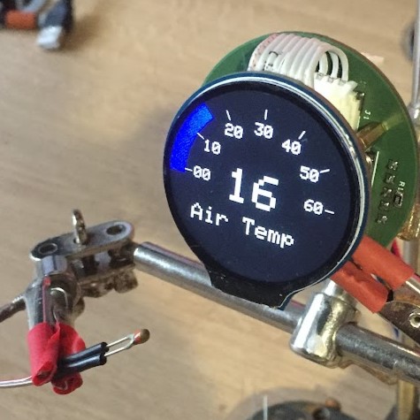
Temperature Gauge

The simplest implementation is an analog sensor, in this example a thermistor. The Arduino reads the analog input from the thermistor and converts it into a temperature using either a lookup table or solving directly using the Steinhart-Hart equation.
With four analog inputs, this setup could be used for monitoring multiple sensor values such as coolant temperature, oil temperature, oil pressure, with a push button to cycle between displayed data.

ardugauge-accel-1.jpg

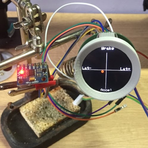
Accelerometer

Connected to an MPU6050 accelerometer/gyroscope via the I2C bus, the ArduGauge can display the longitudinal and lateral acceleration of the vehicle in which it is mounted.

Other Posibilities

Thanks to the SPI interface, ArduGauge has the ability to read vehicle data directly from the CAN bus using an adapter such as the MCP2515.
An SD card reader/writer module can also be connected to the gauge via the SPI bus to enable data logging from the sensors.

Any documentation, design files, BoMs, and schematics for this project can be downloaded here:

DOWNLOADS
×

This website has not yet been optimised for small displays.
For the best experience, please use a PC.